The Kickstarter Project
Normal Functionality
Easter Egg Modes
Simulator
Reprogramming the DigiRule
My DigiRule Software Update
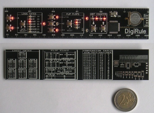
The DigiRule is the result of a Kickstarter project by Bradley Slattery. It is a ruler with some electronic circuitry on it, and has the following features:
The project very quickly reached its target. When I heard out about it, I only just managed to log in in time to pledge money for the last available batch of 10 DigiRules.
During its development, many small improvements were made, often based on suggestions from the backers. To keep the costs down, they were sent out directly from the manufacturer hired to make them. Unfortunately it turned out that the buttons that were used by this manufacturer were more prone to bouncing than those in the prototype, i.e. pressing a button often registered as more than one button press. Bradley released a software update that fixed this problem. The software source code was released too, allowing anyone to change it.
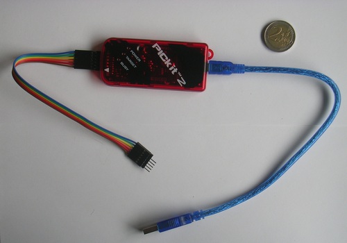
I bought a batch of 10 DigiRules, kept one for myself, sold most of them to my colleagues at work, and gave the rest away to friends. I also ordered a PICkit 2, which connects the DigiRule to a USB port of a PC so that the software update can be applied or otherwise reprogrammed.
Here is a detailed description of its standard functionality. In this and the next section I will also point out the changes I have made to this functionality. You can download my version of the software below.
Press the Gate Select button to choose one of the 7 available logic gates.
Press the A or B buttons on the left to set the input of the logic gate. The
output of the logic gate is shown by the LED marked X, to the right of the
logic gates.
Note: When the NOT gate is selected, button B and its LED are disabled because
the NOT gate only has one input.
When you select a different gate, the A and B inputs are cleared. In my update, the inputs are retained when you change the gate.
The reverse of the DigiRule shows truth tables for all seven logic gates.
Press the FF Select button to choose one of the 4 available flip-flops.
The state of the flip-flop is shown by the two LEDs marked Q
and Q. Initially only Q will be lit.
Press the buttons marked S/J/R/D or R/K on the left to set the input of the flip-flop.
Then press the button marked C (clock) to let the flip-flop execute a clock cycle,
and see whether the output has changed.
Note: When the T or D flip-flop is selected, button R/K and its LED are disabled
because those flip-flops only have one input.
Note that the SR flip-flop indicates invalid output by switching both Q and Q off. The original release of the DigiRule would keep that invalid output when you selected a different gate, and this would lead to wrong behaviour if you selected a flip-flop that could toggle. This was fixed in the first software update, together with the button de-bouncing.
The reverse of the DigiRule shows tables for all four flip-flops.
Press the buttons marked with an up arrow or a down arrow to increment or decrement the value displayed by the 4-bit counter. The counter wraps around from 15 (11112) to 0 (00002) and vice versa.
To access these modes, switch the DigiRule off, hold down the A button, and switch it on. You can now use the up and down buttons to select the mode number shown in the 4-bit counter. When you then press B, the selected mode activates. To exit the selected mode, just switch off the DigiRule.
In my software update you cannot select any unsupported mode numbers, whereas in the original software, it would become unresponsive if any unsupported mode was selected. I have also switched on the Q LED as an indication that DigiRule is in the mode-select state.
If mode 1 is selected, the DigiRule acts in exactly the same way as if it was switched on normally, without the mode selection.
If mode 2 is selected, the DigiRule acts normally with regards to the logic gates and the flip-flops, but the binary counter now operates in Gray code. This means that pressing the UP or Down buttons will only change one bit of the 4-bit counter, while it still cycles through all 16 possible states.
If mode 3 is selected, the 23 LEDs flash at random. You can press the Up button to speed it up or Down to slow it down.
If mode 4 is selected, the LEDs in the logic gates section become a
7-bit serial in shift register. Press A to select the input to be used.
Press the Gate Select button to shift the register downwards, where the
input from A is entered at the top. Press B to clear the register.
Note that in my update, the X LED is always kept on to make it
impossible to have all LEDs off, because that would allow you forget to
switch off the DigiRule when you are done with it.
If mode 5 is selected, all LEDs are switched on.
If mode 6 is selected, the 7 LEDs in the logic gate section flash
in such a way that when you quickly move the DigiRule sideways, a
pattern appears. Press B to change which of the three available
patterns are shown. The patterns are: smiley faces, a wave form, or
the text "THE DIGIRULE RULES!".
Note that the smileys and the wave form are symmetrical, so you
can simply wave the DigiRule back and forth, whereas with the text
you can only see it when the DigiRule is moving left to right.
In my update there are some small fixes to the patterns displayed.
If mode 7 is selected, the 4-bit counter will flicker and then
display a random number from 1 to 6 inclusive, like throwing a die.
Press B to roll it again.
In my update you can choose how many sides the die has. Press the Up
and Down buttons to select any number from 2 to 31. The Q LED acts as a
fifth bit of the counter. When you next press B, the number will be chosen
at random from the selected range.
If mode 8 is selected, a light will start moving up and down the 7 logic gates. If you press B when the light is in the middle (at the XOR gate) then you gain a point. Your score is shown in the 4-bit counter. The light will move faster as your score gets higher. If you press B when the light is not in the middle, your score is reset to zero, and the light will once again move at the starting speed.
If mode 9 is selected, the LEDs in the flip-flop section become the output of a 4-bit logic unit. Use the Up/Down buttons to select a number in the 4-bit counter. Press A to store that number as input A. Again, use the Up/Down buttons to select a number in the 4-bit counter. Press B to store that number as input B. Press the Gate Select button to select any of the six gates with two inputs. The output of that gate, with the two selected number as input, is shown in the flip-flops section, with the least significant bit at the bottom.
This mode is only available in my update.
If mode 10 is selected, the LEDs in the logic gate section show a random
pattern. The aim of the puzzle is to switch all the lights off. Press A
or B to cyclically shift the lights up or down. Pressing the Gate Select
button toggles a particular set of lights. When all the lights are off
you get a point, and get to try again but now a different set of lights
is toggled by the Gate Select button.
This mode is only available in my update.
If mode 11 is selected, a 15-bit counter is displayed that automatically
increases. The low bits are shown in the 4-bit counter, the next higher
bits in the flip-flop column, the highest 7 bits in the gates column. Press
the up or down buttons to increase or decrease the speed at which the counter
increments.
You can play with the DigiRule right here. Click the buttons and see what it does. You can even access most of the Easter egg modes by clicking the off switch to switch it off and then on again.

On Bradley Slattery's web site he has provided links to all the software he used to create the DigiRule. For re-programming it, all you need are:
The PICkit2 device that I used is the cheap clone that Brad recommended ($9 including shipping!) and comes with a ribbon lead that connects it directly to the DigiRule. The ribbon does have 6 pins at the end, whereas the DigiRule has a connector with 5 holes. Simply remove the sixth pin from the end of the ribbon, leaving the five that are nearest to the triangle marker on the output of the PICkit2 device.
To upload a compiled hex file to the DigiRule, use these steps:
My updated version of the DigiRule software can be downloaded here:
It is based on the 2015-12-15 version from Bradley Slattery's web page (which dealt with the button de-bouncing and fixed a flip-flop bug), but with the following additional changes:
Updated 2015-12-29 with the following bug fixes:
Updated 2016-01-05:
© Copyright 2015-2016 Jaap Scherphuis, digirule a t jaapsch d o t net.
Back to Home Page